Auto 4% OFF AUDI C6 Q7 A6 Steering Module Repair J518 ELV Emulator with VVDI Prog Dedicated Programming Cable

We have Warehouses in the EU,US,UK,CN. No customs fees.
If you need best price, pls contact Emily:
Skype: VVDIfactory.com
Whatapp: +86 13559259147
Email: sales@vvdishop.com
Product Description
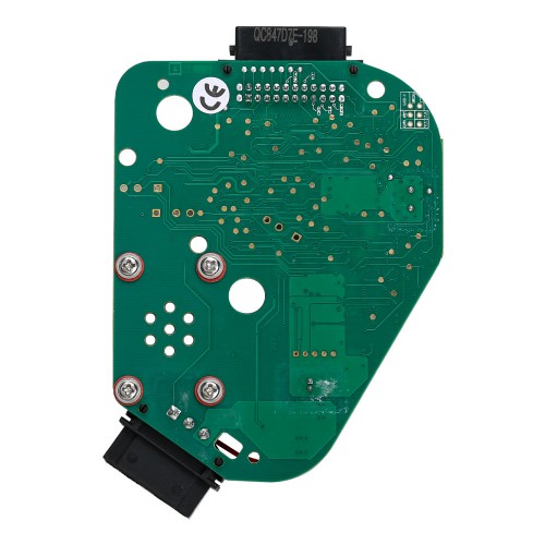
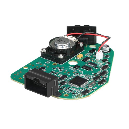
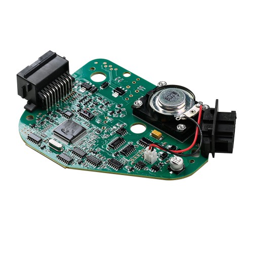
Highlight for Audi Steering Module J518 ELV Emulator:
2. Stable and durable, No Vulnerable components such as relays, microswitch and motors on it.
The emulator without lock or on lock function, if need the same function as the original J518 Module, please buy the J518 Replacement
Please note:
1.Only need to write EEprom data, no need write other data like flash.etc.
2.Please choose only the "j518(2010-)0L01Y"in VVDI Prog software, no matter your car model before 2010 or after.
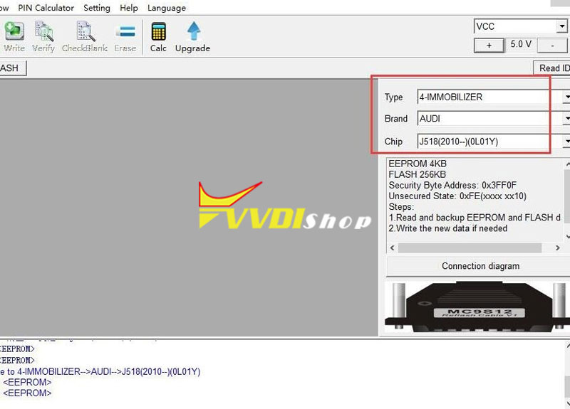
Change steps:
1. Read out the EEPROM data from the original J518 module of your car (the emulator was already with flash data)
2. Write the EEPROM data you got in Step 1 into the emulator (if the original J518 MCU mask is 0L01Y, write the EEPROM data you got from step1 into the emulator directly;
or if the MCU mask of the original J518 is 1L59W/3L40K, you need to send EEPROM data to an expert to transfer EEPROM data when you write into the emulator directly. We don't provide the service)
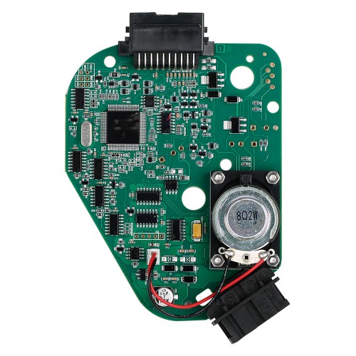
the J518 replacement PCB
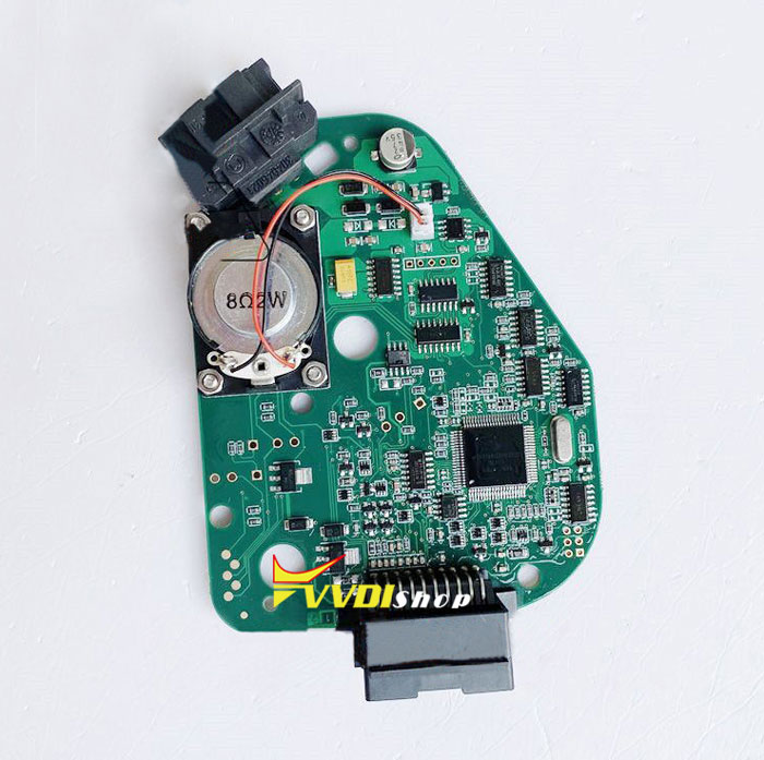
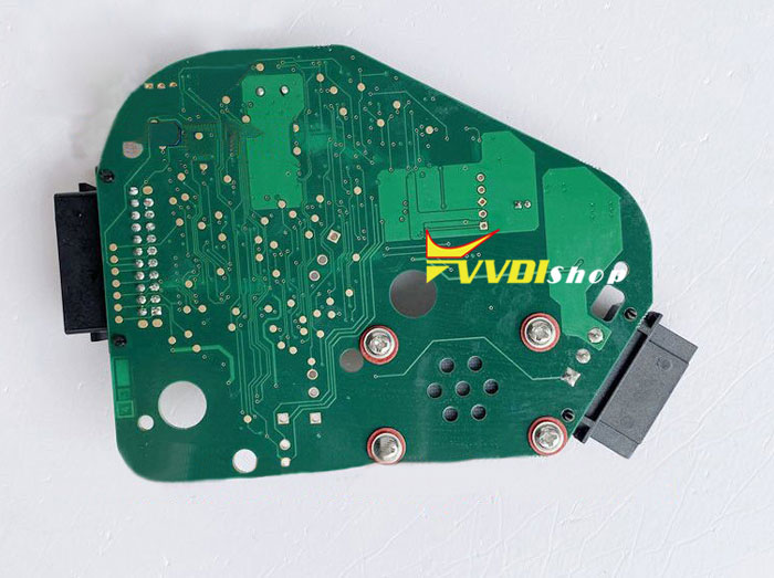
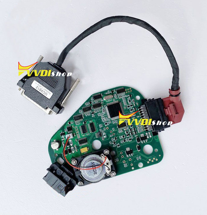
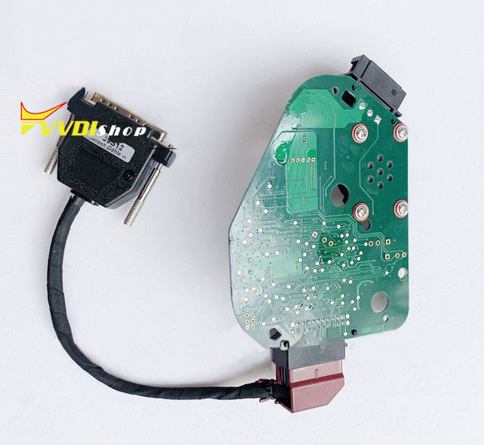
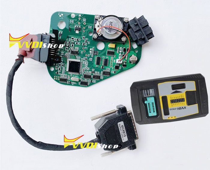
Free download J518 Flash that is in the emulator
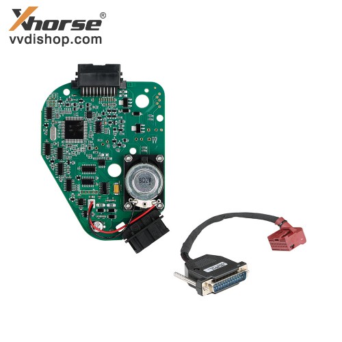
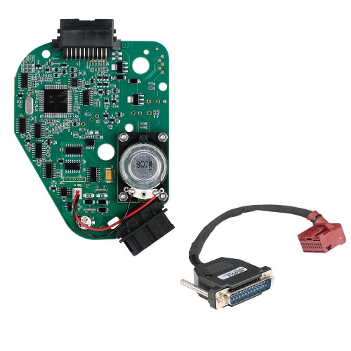
Package includes:
We have Warehouses in EU,US,UK,China,Russia,Belgium. No customs fees.
If you need better price, please feel free to contact us.
Skype: VVDIfactory.com
Email: sales@vvdishop.com
Tech Support
Here is the AUDI C6 Q7 A6 Steering Module Repair J518 ELV Emulator 256,128 simulate board operation instruction.
Do backup original eeprom data in case of lost data before operation. Read and save data.
If your car ELV has 9S12DG 128 CPU, the operation steps are as follows.
9S12DG 128 CPU operation steps:
1.Read and backup original EEPROM data.
2. Paste EEPROM data to EEPROM 2K-4K folder.
Double-click EEPROM Converter-x86 application.

You will see the original 2K file converted to 4K.
You will see the file is 4K


Only double-click this program once. Do not repeat.
If 2k file does not contvert to 4K, right click and run EEPROM Converter-x86 as asministor
3. Connect flashing wire and write the converted 4k eeprom file.
For simulator chip 256, select J518(2010)(0L01Y) in vvdi prog software
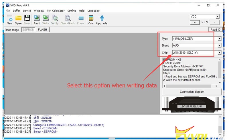
Each ELV emulator board contains both eeprom data and FLSAH data, so usually you just need to write Eeprom data. If not, you can write original eeprom data and the FLASH data in the emulator.
If car ELV has 9S12DG 256 CPU, the operation steps are as follows.
Read out and save the original eeprom data, and write it directly to the simulator.
without horn wiring connection
red (thick) =VCC
black (thick) =GND
yellow =RST
purple =BKGD
green =XCLKS
White =CLK
black (fine) =GND-C
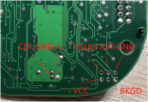
with horn wiring connection
follow same wiring diagram as without horn above
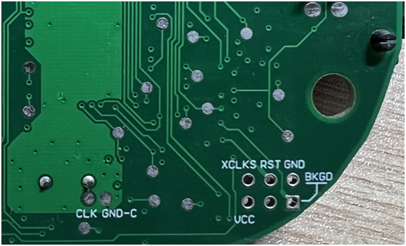
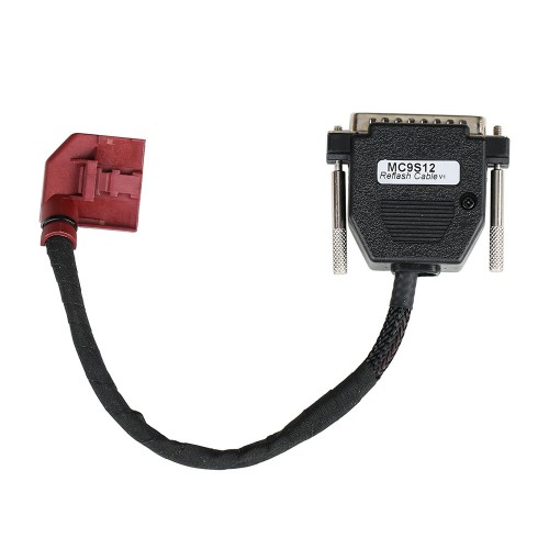
With the VVDI Prog Dedicated Programming Cable, you can connect ELV emulator without soldering, directly insert into the 20pin port.
Attention:
Better put J518 ELV emulator to car after write data.
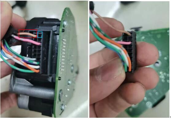
In the test platform test, better check the wiring of 20Pin port. Some test platforms will conflict with the 20pin port which leads to the chip being corrupted.
Error wiring: 10 (red) should be in position 20 (blue), as shown in the figure.
